Scientific Instruments
|
|
Conductive thin film production device for electron microscope sample preparation
Osmium Plasma Coater |
|
Catalogue Download |
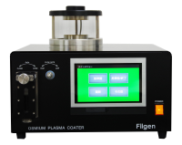
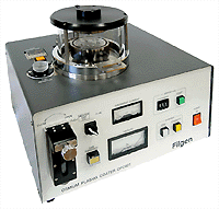
Osmium Plasma Coater(OPC) is the plasma coating device that uses the DC
glow discharge method to coat conductive thin film mainly for SEM samples.
|
|
  |
|
 Benefits of Osmium Plasma Coater Benefits of Osmium Plasma Coater

|
| Operability |
Osmium Conductive Film |
Plasma-Polymerized
Naphthalene Hydrocarbon Film |
| ● |
Simple Automatic Operation
(Only need to set the thickness of the film and then push start button) |
| ● |
Detachable Osmium Reservoir
The sealed structure of the reservoir allows cryopreservation |
| ● |
Easy Confirmation of The Remaining Amount
(A small view port allows confirmation of the remaining amount of the OsO4/naphthalene
crystal.) |
| ● |
Short Coating Time
(a few nm/a few seconds) |
| ● |
High Security
(An interlock circuit is equipped.) |
|
| ● |
No Granule
The osmium thin film is not granular. |
| ● |
The microstructure of the specimen surface can be faithfully molded.
OsO4 will sublimate before coating process. |
| ● |
No Heat Damage
The coating process is at room temperature. Thus, the specimen will not
go through a heat process. |
| ● |
No Electron Beam Damage
The melting temperature of Osmium is 2700℃, whick is much higher than the
ones of Pt or Pd. So osmium conductive metal coating is not damaged nor
deformed by heat when exposed to strong electron beam. |
| ● |
No contamination
In the regative glow phase domain of the DC glow discharge, where only
osmium metal molecules are positively ionized, highly concentrated positive
ion osmium molecules adhere uniformly, deposit densely and form the thin
layer in molecular level on the specimen which is electrically insulate. |
|
| ● |
Toughness
The film can withstand the gallium ions that used in FIB(Focused Ion Beam)
system. |
| ● |
Heat-resistance |
| ● |
Insulation |
| ● |
No Granule
The plasma-polymerized hydrocarbon film is not granular. |
| ● |
The microstructure of the specimen surface can be faithfully molded.
Naphthalene will sublimate before coating process |
| ● |
No Heat Damage
The coating process is at room temperature. Thus, the specimen will not
go through a heat process. |
| ● |
No Electron Beam Damage |
|
|
 Principle Principle

|
A small amount of osmium tetroxide(OsO4)gas / naphthalene gas(C10H18) is introduced into the small gas reaction vessel that equips with an anode
plate and a cathode plate.
Then, in the gas reaction vessel, when a DC glow discharge is generated
under a thin sublimation gas pressure, the osmium metal molecules excited
by the collision of electrons instantaneously become plasma between the
two electrodes. The positive column and the negative glow phase are separated,
and the blue-violet light of the negative glow phase emits.
At the same time, the positive ion metal molecules instantly adhere to
the surface of the specimen, which is placed in the negative glow phase
area on the cathode plate, and an osmium metal thin film/plasma-polymerized
film(naphthalene) is formed.
With an osmium metal thin film on the surface of the SEM specimen, an extremely
clear image can be obtained. |
 Application Application

|
| Conductive Ultra-thin Film |
| ● |
Observation of the ultrafine structure of insulators by FE-SEM |
| ● |
Quantitative analysis of top surface of insulators by ESCA or AES
(Auger Electron Spectroscopy) |
| ● |
Enhancement of conductivity for TEM specimen |
| ● |
Static prevention treatment for AFM specimen |
| ● |
Antistatic treatment for STM specimen |
| ● |
Etching(Mixed gas method only) |
|
| Osmium Thin Film |
| ● |
Conductive thin film for SEM specimen |
| ● |
Prevention of contamination for SEM/TEM specimen |
| ● |
Protective film for AFM specimen |
| ● |
COnductive protective film for SPM specimen |
| ● |
Protective film for SPM cantilever |
|
|
|
| Plasma-Polymerized Film (TEM image) |
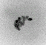 |
Direct Magnification:×100,000
Coating Material:Naphthalene
Coating Thickness:10nm |
|
 The Merit of Automatic Operation The Merit of Automatic Operation

|
Our current model of the osmium plasma coater (we have manual model in
the past) is fully automatc.
After placing the specimen on the sample stage, closing the gas reaction
vessel and setting the thickness of the film, you can coat a film simply
by pressing the start button.
Since there is no complicated manual operation, there are no artificial
film thickness errors. Thus, the current automatic model has excellent
repeatability and higher safety.
| Comparison of operability |
Automatic Model
(current model) |
Manual Model
(old model) |
| Preparation |
Place the specimen in the gas reaction vessel. |
| Coating |
Vacuuming |
Press the START button, then the coating process will proceed automatically.
Automatic coating procedure
1. 「Vacuuming」
2. 「Introducing Osmium gas」
3. 「Adjusting Osmium gas flow」
4. 「Controlling the film thickness(Coating)」
5. 「Releasing Osmium gas」
Since the film thickness can be set in a nm unit, the control is very simple.
Because an interlock circuit is equipped, the gas reaction vessel will not open if the "releasing
the Osmium gas” step is not done.
|
Vacuum the gas reaction vessel to the specified vacuum degree, which should
be confirmed visually. |
| Introducing the Osmium gas |
Introduce the Osmium gas by rotating the valve. |
| Adjusting the Osmium gas flow |
Adjust the Osmium gas flow manually by the rotary valve, while checking
the vacuum degree of the Osmium gas or other indicating meters. |
Controlling the film thickness
(Coating) |
Since the film thickness is determined by the correlation between the current
value and time of discharge, rotate the rotary valve manually to adjust
the current value. |
| Exhausting the Osmium gas |
Close the valve to stop the introducing of Osmium gas, then fully open
the rotary valve manually to release the gas from the gas reaction vessel.
Because this model do not have an interlock circuit, it is possible to
open the gas reaction vessel without conducting the "releasing the
Osmium gas" step. |
|
 About the Osmium Reservoir About the Osmium Reservoir

|
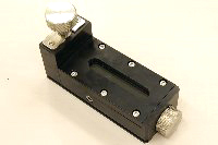
Osmium Reservoir |
|
|
 |
Osmium Tetroxide ampule
(OsO4) |
|
| ① |
Fully open
(When attaching to the device) |
・・・ |
Staining gas is filled up to the front of the solenoid valve.
(Not detachable) |
| ② |
Half-closed
(When releasing gas in the pipes) |
・・・ |
By turning the gas introduction knob to the marked line and opening the
solenoid valve, the staining gas in the introduction pipes can be released.
(Not detachable) |
| ③ |
Fully closed
(Detachable state) |
・・・ |
By completely closing the gas introduction knob, the Osmium reservoir is
sealed and can be safely removed from the Osmium plasma coater. |
|
|
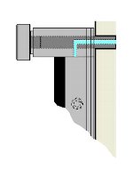 |
①Fully open
(When attaching to the device) |
|
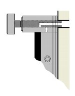 |
②Half-closed
(When releasing gas in the pipes) |
|
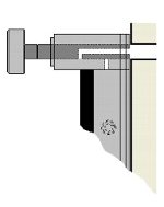 |
③Fully closed
(Detachable state) |
|
|
|
When the Osmium reservoir is sealed, it can be detached safely.
・Osmium tetroxide(OsO4) ampule can be placed inside the reservoir, and the ampule can be cut inside.
・When the reservoir is at fully closed state, it can be removed and ready
for cryopreservation.
・It can also minimize the loss due to osmium sublimation when it is not
in use.
・There are two types of osmium tetroxide ampoules, which have 100mg and
500mg OsO4 each. |
|
|
| Product |
Osmium reservoir |
| Model |
OPC-ORV |
| Outer Dimension |
70(W)×45(D)×120(H)mm |
| Weight |
About 480g |
|
|